As published in antennex Dec. 2001
The 40 Meters band stealth vertical antenna by K7ZB
“You’re 30dB over 9 here…” So goes the consistently fine signal reports received from around the USA and beyond – on 40 meters at the peak of Sun Spot Cycle 23. The most common antenna used in ham radio mounted over poor desert soil conductivity still performs beautifully!
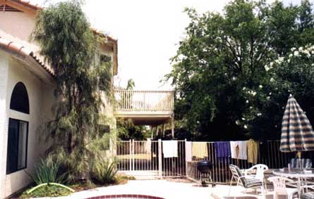
This is the view of our second floor deck as seen from the closest street. The need for a 40 meter antenna that would perform well and not violate the spirit of the Home Owner’s Covenants protecting the aesthetics of the neighborhood was the driving force behind the design of this vertical.
This antenna was designed to provide low angle radiation for good DX performance during the night time hours. DX on 40 meters is best when the local sun is down and this makes it convenient to use the cover of darkness to hide the size of a quarter-wave antenna. Especially one which is mounted 12 feet above ground which puts the top of the vertical at nearly 50 feet!
The basic concept is to mount a standard 1/4 wave vertical element on a swivel mount, secured to the deck railing. The mounting must be extremely secure when the antenna is in the upright position. It should also be easy for one person to put up or take down in less than 5 minutes. This design meets these criteria with excellent results.
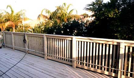
The 40m vertical in its down position rests along the bottom of the far side deck railing. It is supported by plastic coated hangers of the type sold in hardware stores for hanging bicycles, etc, on garage walls. These hangers also make excellent supports for the antenna in the intermediate position for extending the telescoping top section and for supporting the vertical in the upright position.
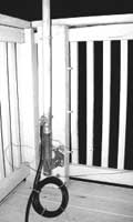
Shown below is a view of the vertical with the telescoping top 5′ section removed and stored in the down position. The swivel assembly has a spring-loaded locking pin which secures the base in either the upright or down positions. Putting up the antenna is simple: the top section is secured with a wing nut then the vertical is walked up hand-over-hand into the upright position and locked in place with the pin. The hanger also stabilizes the antenna so it does not sway in light wind.
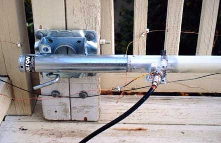
The swivel assembly has been modified to support the vertical base element. Its load rating is well in excess of the load imposed by the vertical. Since the 35′ – 7 1/2″ vertical is only intended for use during good weather conditions it is only guyed with two light guy lines to ensure that in case something did happen to the antenna while up, it will not fall across neighbor’s property. In our neighborhood there are no above-ground wires for power, cable TV or telephone, so there is no possibility of a crossed-wire mishap. The coax attachment is made through an SO-239 connector mounted on an acrylic plastic block drilled and U-clamped to the base tubing. Also visible are the two radials connected to the shield of the coax connector. The two radials are 33′ long, and slope from 12 to 7 feet above ground at their end. They slope because that’s the available tie point height in the yard. The radials are oriented 145 degrees apart – not quite the 180 degrees desired but close enough. The EZNEC antenna azimuth plots do show the minor skewing of the pattern due to the asymmetric radial placement, but this has little effect on its performance.
The net active dimensions (not including the length inserted into lower elements) for each element of the vertical are as follows:
- Base element: 11′ 5″ (1 3/4″ Dia. Al tubing)
- 2nd element: 10′ 2″ (1 1/4″ Dia. Al tubing)
- 3rd element: 5′ 7″ ( 3/4″ Dia. Al tubing)
- 4th element: 4′ 11 1/2″ (1/2″ Dia. Al tubing)
- 5th element: 3′ 6″ (3/8″ solid Al rod)
The tubing diameters were based on what I had available. Good mechanical design technique should be used in attaching each element securely into the lower one.
This antenna does bow substantially when being put up and down. This droop could be minimized by going to a higher strength alloy. The best strength-to-weight ratio for vertical tubing is probably titanium-aluminum alloy, although it costs substantially more than the material I used.
Raising and lowering 35 feet of aluminum tubing up over one’s head in low light conditions leads to safety considerations. I wear a hard hat and safety glasses when raising or lowering the vertical.
Shown below is a night-time photograph of the vertical in the upright position. The stabilizing hanger is seen approximately 2′ above the swivel assembly. Notice a 6 turn coax loop in the line which serves to help keep RF out of the shack – which is about 20′ from the vertical. The RF exposure on 40 meters with 500 watts output is within the FCC’s Maximum Permissible Exposure limits.
An advantage of verticals mounted above ground like this one is the safety aspect of proximity to RF-hot radial wires or vertical elements. Our yard is walled and the RV gate kept locked, and the access out to the deck is past my operating desk – so there is little danger of anyone’s unexpected exposure to hot wires.
Brian KD7Z helped with the design concept when he directed my attention to a Hints & Kinks article in QST (May 2000, page 56) that featured the fold-down mobile-antenna mount design of KB5YA. It was this use of the swivel jack that led us to conceive its use for a deck-mounted 40m vertical design.
Dave provided EZNEC computer simulations for the vertical dimensions used here, which when implemented were right on target.
 The photo is of the vertical in daylight – up just long enough to take the picture to show how it looks at night! You can faintly make out the guy lines and one of the radials running out to the spot where I was standing to take this picture. Above the doorway on the deck is the coax feedline to the center insulator at the eave under the roof peak for the 75m antenna.
An excellent reference for understanding vertical antennas is provided by L.B. Cebik, W4RNL. Dr. Cebik is an authority on antennas and his website contains a vast amount of excellent information. The webpage specifcally covering verticals is shown below.
Original article by K7ZB
Originally available at pages.zdnet.com/radio_k7zb/id8.html
[tags]ham radio, antenna,amateur radio[/tags]